
CABLE TESTING AND DIAGNOSTICS
The Tan Delta technique is a powerful tool. Its goal is to support operation and maintenance technicians and managers. The technique makes it possible to obtain accurate information about the condition of medium voltage insulated cables, whether in a power utility, a large industrial plant, or in wind and solar photovoltaic power plants.
The information we obtain from tan delta analysis has the potential to guide maintenance actions, increasing cost predictability, operational planning, allocation of resources for preventive maintenance, as well as contingency planning (in case of failures) and cable replacement planning when necessary.
We use Tan Delta measurements to assess the levels of aging and degradation of cable insulation. In addition to inferring the aging level of the materials, the technique can also indicate various irregularities, such as the existence of defects that produce partial discharges, water ingress, treeing, among others.
We perform the tests by applying electrical voltage to the insulation at VLF (Very Low Frequency) in different voltage levels, usually between 0.5Uo and 2Uo, for just a few minutes. At each level of applied voltage, we carry out sequential measurements to evaluate the average behavior of the tan delta and its stability.
The reference standard we most widely use for this purpose is IEEE Guide 400.2 – 2024. In this standard, the behavior of the Tan Delta as a function of the voltage level is also an important analysis parameter. As in other offline methods, one of the requirements for performing the tests is disconnecting the cable terminations.
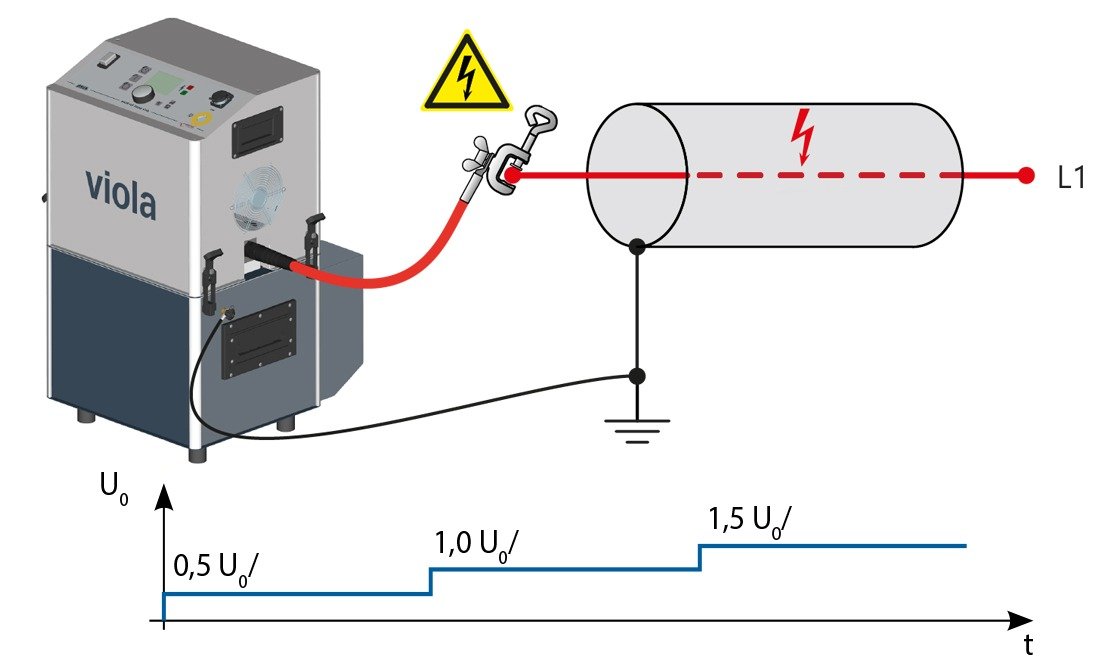
The illustration above shows the diagram of the setup used for performing Tan Delta tests. The cable from the viola TD, the BAUR equipment that performs the measurements, connects to the conductor of the test object. The shield remains grounded. The equipment applies voltage in three steps: 0.5, 1, and 1.5 times the phase-to-ground rated voltage. During each voltage level, the instrument performs about 6 to 20 tan delta measurements. We calculate the average and stability for each voltage level, as well as the variation in the average tan delta between the highest and lowest applied voltage levels.
An insulated cable is a capacitive system, since it has two conductors (the main conductor and the metallic shield) with an insulating medium between them. In this way, when we apply voltage to the material, both electrodes become polarized and the potential energy is stored in the electric field. A perfect capacitor simply stores this energy without any loss, without heat generation or any other effect. In principle, this energy can be fully recovered in the future when the perfect capacitor is discharged.
However, all real materials present some energy loss during the polarization and depolarization process, whether due to heating or any other mechanism. This energy dissipation may be very small in certain setups, but it always exists. A cable behaves like a real capacitor, and the more aged the insulation is, the greater the energy dissipation in this process. We can see, in the figure below, the equivalent electrical circuit for cable insulation.

In the diagram shown above, it is possible to observe that the insulation behaves like a capacitor, with a dielectric medium between two conductors, the shield and the main conductor. Considering a perfect insulation, the resistance R of the insulation would tend toward infinity, making the resistive component of the electric current, IR, zero. Considering a real insulation, the resistance is measurable, as is the electric current, which is different from zero. The dissipation factor is the ratio between the resistive and capacitive components of the electric current. For a healthy cable, the dissipation factor is as low as possible, according to the characteristics of the materials used.
Considering a healthy cable subjected to a potential difference, an electric current will flow in the direction of the electric field vector. This electric current will have two components: the capacitive and the resistive. The insulation resistance is very high for a healthy cable, so the resistive component of the electric current will be very small (according to Ohm’s Law).
The Tan Delta / dielectric loss factor, also known as the dissipation factor, is defined as the ratio between the resistive and capacitive components. The more aged and deteriorated the insulation is, the lower its resistance will be and, therefore, the higher the dissipation factor (which is synonymous with Tan Delta).
We can represent the components of the electric current in a phasor diagram, as shown in the figure below (keeping in mind that the resistive electric current is always in phase with the applied voltage, and the capacitive electric current is 90 degrees out of phase). Since the components of the electric current vector, capacitive and resistive, do not point in the same direction, it is possible to construct a right triangle, in which the tangent of the angle delta formed with the vertical axis is exactly the definition of the dissipation factor.

The cable insulation system, as it undergoes thermal cycles or remains in operation for extended periods, will show natural aging and degradation. The dielectric strength of the insulation will decrease over time. This can correlate with the tan delta, such that the strategy is to monitor the Tan Delta through periodic measurements as a predictive tracking method, allowing the inference of insulation quality and anticipating failure risks.
Although the Tan Delta increases continuously with cable aging and degradation, when analyzing values for new cables with different types of insulation, it is possible to observe that the orders of magnitude are relatively different. In general, XLPE-type insulation presents a much lower Tan Delta than EPR insulation. In fact, the Tan Delta depends intrinsically on some characteristics presented below.
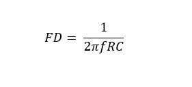
Where f is the frequency of the applied voltage, R is the insulation resistance, and C is the capacitance, with the capacitance given by:
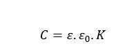
Where ε is the dielectric permittivity of the insulation, ε₀ is the vacuum permittivity, and K is a form factor.
The analysis of the equations above shows that Tan Delta depends on the frequency of the voltage source, but also on the dielectric permittivity of the insulation, which is a characteristic property of the insulating material. That is, if an EPR, XLPE, or oil-impregnated paper insulation is considered, it is not possible to apply the same evaluation criteria, since each material, even when healthy, will exhibit different expected behavior.
In fact, even new cables from different manufacturers usually present slightly different results, even if they use the same type of insulation. So, how should the values obtained for Tan Delta be evaluated? There are several approaches, starting with the most common one, which adopts the criteria from the IEEE 400.2 guide.

BAUR viola TD is an device recommended for performing VLF (Very Low Frequency) withstand test and dissipation factor (Tan Delta) test on insulated cables rated up to 20/35 kV.
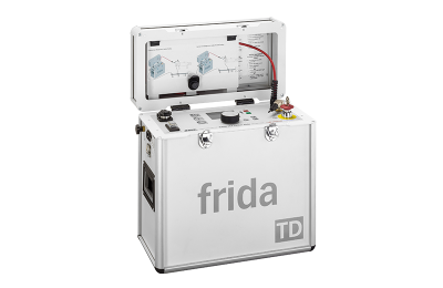
BAUR frida TD is the recommended device for performing VLF (Very Low Frequency) withstand test and dissipation factor (Tan Delta) test on insulated cables rated up to 12/20 kV.

The decision to replace a medium-voltage cable is rarely...

Tan Delta, also known as the dielectric loss factor...

Whether during the commissioning stage or operation, it is...