
CABLE FAULT LOCATION
Even with all the technology available and the diagnostic techniques that exist today, medium-voltage networks can eventually fail. For that reason, it’s essential that the asset operations and maintenance team has a contingency plan. This makes it possible to locate faults in medium-voltage networks quickly and accurately in order to restore the affected electrical systems.
The cut-and-test method was the first technique for locating faults in underground power networks to appear on the market. It involves finding the midpoint of the faulted circuit, cutting the insulated medium-voltage cable, and performing a voltage test on both sides. If the fault shows up on one side, the procedure must be repeated—meaning the midpoint of the faulted section must be found again and the cable cut to test both sides. With this method, the cable must be cut as many times as necessary until the fault point is found.
Considering that more than 95% of faults in underground power networks originate from accessories, meaning splices and terminations, the cut-and-test method introduces several weak points into the circuit. The result is reduced system reliability. Keeping this in mind, equipment engineering has developed other, more efficient and less invasive techniques for fault location in buried medium-voltage networks, where it is not necessary to make systematic cuts in the cable.
The IEEE 1234 guide, “Fault-Locating Techniques on Shielded Power Cable Systems,” and CIGRE Technical Brochure 773, “Fault location on land and submarine links (AC & DC),” are the international references for best practices and techniques to properly locate faults in underground power networks.
Fault location on an insulated cable installed in an underground power network is not a trivial process. On the contrary, it follows a traditionally established methodology, outlined in the figure below:

Below, we will discuss each of these steps, going through the most recommended procedures and tests for each phase.
The first step is to perform tests to confirm and characterize the fault in the isolated medium-voltage network. The information obtained in this step will guide the procedures adopted in all subsequent phases, as well as determine which equipment will be required during the process. Applying the most appropriate methods reduces the time needed to locate faults in medium-voltage networks and reduces the damage/stress produced on the cables.
During the characterization stage, it is important to identify the type of fault and the breakdown voltages in the cables, as shown in the examples below:
Short-circuit faults
Short-circuit faults are the most common after installation and commissioning. They can be phase-to-ground or phase-to-phase, depending on the type of cable used in the installation. These faults immediately operate the protection system, typically with high transient currents and overvoltage on the other system components.
Open-circuit faults occur when one of the cable conductors is severed. Severing is commonly associated with theft or the use of tools and machinery that mechanically damage the cables. When only the shield is severed, the protection system is not operated.
Among the network faults we may encounter, faults in the cable jacket typically occur during installation. They do not operate the protection system and do not interfere with the cable’s functionality, but they usually increase the rate of asset degradation.
To perform fault characterization tests, the cable terminations must remain disconnected. The ideal sequence for performing the tests depends on the incident history and the information available, but it generally is not an important factor, since these are relatively brief procedures. See the table below.
| Procedure | Analysis |
| Measurement of resistance between conductors and metallic shields | The resistance between conductors and the shield should read out of range or very high. Usually performed with a standard multimeter, this measurement makes it possible to infer the resistance of a phase-to-ground short-circuit fault. |
| Measurement of resistance between adjacent conductors (three-core cables) | The resistance between adjacent phases should read out of range. A low resistance indicates a phase-to-phase short circuit. Usually performed with a standard multimeter. |
| Breakdown voltage determination | In this test, a medium-voltage test set with a capacitive source is connected to the cable conductor. The source voltage is increased until dielectric breakdown occurs at the fault point. When this happens, the energy stored in the source capacitor is discharged, and the voltage drop can be seen on the equipment voltmeter. The voltage immediately before the drop on the voltmeter is the fault breakdown voltage. |
| Loop continuity measurement | When open-circuit faults are suspected, you can connect conductors of adjacent cables at the cable end, forming a loop (between companion phases or between conductor and shield). Resistance/continuity is measured at the other end of the cables. If one conductor is broken, the loop will have no continuity, and infinite resistance will be measured on the multimeter. |
| Time-domain reflectometry (TDR) test | When a network fault-locating instrument—a reflectometer—is available, it is recommended to take a measurement in “Echo” mode, since it can more practically and precisely indicate the presence of cable severing, impedance irregularities, among other issues. Depending on the type of fault, the procedure will not only characterize the fault but also provide an estimate of its location. |
After characterizing the fault, we carry out the pre-location methods. In this step, we locate faults in medium-voltage networks approximately. It is perhaps the most critical step in the entire process, because it typically involves a greater need for technology and trained teams.
Good fault pre-location in networks ensures greater agility in the corrective maintenance process, while poor or difficult pre-location results can severely delay system restoration. In this step, we apply the methods described in detail in the IEEE 1234-2007 guide, the CIGRE WG B1.52-773 brochure, and extensive literature on the subject.
When choosing the appropriate method, we must take into account the type of fault, the breakdown voltage, its impedance, as well as construction characteristics and the available equipment. You should always opt for the fastest techniques that generate the least collateral damage to the cables.
The methods most commonly used for jacket faults and unshielded cables are those based on bridge measurements, such as the Murray method. For short-circuit faults in shielded cables, time-domain reflectometry–based methods performed with the Syscompact 400 portable equipment usually yield faster results.
After the fault pre-location stage in the network, the distance from the measurement point to the fault position will be relatively well estimated. However, if the crew does not know the cable route, or if the cables were installed along a non-linear path, the information obtained may not be immediately useful. This happens because the crew will need to spend excessive time searching for, or carrying out, the next step of the procedure.
Sometimes we install cables with significant slack or along a curved route. An indication of 200 meters in the pre-location stage can be significantly different from a 200-meter distance to the cable end.
There are various reasons why the cable route may be unknown. A very old installation may not have the project drawings available, or a later civil works project may have modified the electrical network, producing changes to the design that are not always documented after completion. Existing physical markings on the ground surface can also fade over time.
If the route is unknown, an additional step will be necessary to enable corrective maintenance. For this, you need to use a specific piece of equipment to determine the cable route. This equipment consists of a transmitter and an audio-frequency sensor, such as the BAUR Cable Locator – CL 20 instrument.
The method consists of injecting an electrical signal from the transmitter into the de-energized cable, at a known frequency that can be adjusted from hundreds to thousands of hertz, at one of the terminations. The injected signal is carried along the entire length of the cable and can be detected with the sensor, with higher intensity, over the cable route. The sweep is performed starting from the termination, collecting the cable position data along the route.
The pinpoint location stage provides accuracy within a few centimeters, allowing trench opening, if needed, as well as the subsequent repair. The pre-location methods previously used provide reasonable accuracy on the order of 1% to 7%, but for long sections, this uncertainty range can be extremely large.
For example, for a 2,000 m section, the uncertainty would be on the order of 20 m to 140 m, which is a relatively large length for trench excavation. That is why pinpoint location methods are necessary. IEEE 1234-2007 and CIGRE WG B1.52–773 are good sources for a more detailed review of pinpoint fault location techniques.
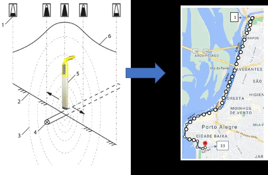
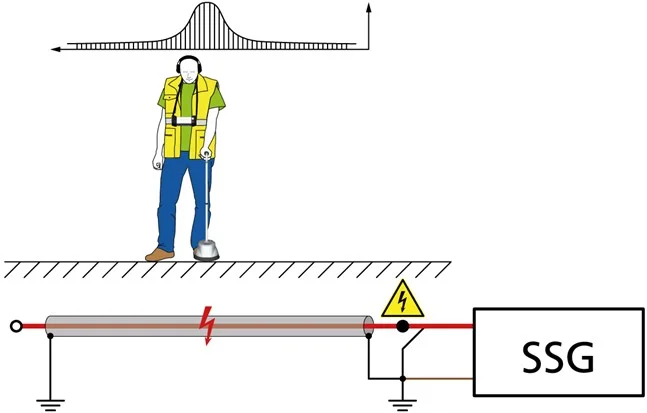
Among the available methods, the one most commonly used for locating faults in medium-voltage networks is the acoustic method, using shock waves. The method consists of sending medium-voltage pulses, using an appropriate source to produce arcing at the fault with the resulting emission of sound, electromagnetic signals, and light.
A ground microphone, such as the BAUR protrac® instrument, can be used to capture the sounds generated by the arcing, or specific sensors can be used to measure step voltage in the soil. Depending on the fault point, when the cables are installed on cable trays or are overhead, it is possible to locate it visually, including by seeing the light signal.
In this step-by-step guide, you can learn in a practical way how to determine the direction and depth of an insulated cable route using the protrac®:
In this tutorial, we show how to perform fault location in medium-voltage networks on insulated cables with twisted, unshielded phases using the protrac® identification system:
It’s important to note that shock waves produce a sudden energy dissipation at the fault point, with significant currents flowing through the conductors. We should minimize their use as much as possible, because they can cause stress and damage to the insulation, reducing the asset’s service life. This happens mainly when shock waves are applied for an extended period of time.
Prolonged use of shock waves can also cause heating of the equipment used, damaging high-voltage components and potentially leading to high repair costs. So, once again, it’s important to emphasize that the key to fast and efficient fault location is performing good pre-location.
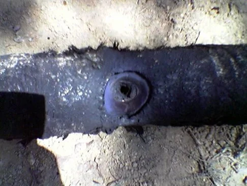
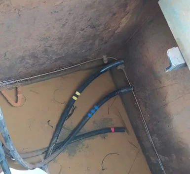
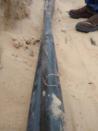
After confirmation and trench opening, the repair is finally carried out. The procedures involved vary depending on the specifics of the defect or fault, but they usually consist of cutting out part of the cable and then installing accessories—splices or terminations. Each manufacturer has particularities in its accessory designs, so it is essential to perform the work according to the item’s manual.
Many people see accessories as weak points in medium-voltage insulated cable systems. However, when properly installed, they should have durability similar to cable sections without accessories. Still, it’s possible for accessories to end up below the ideal standard, which can introduce weaknesses into the system. This can happen due to a lack of skilled labor during emergency response work. Another reason can be the high cost of hiring qualified labor that is available.
Most accessory manufacturers offer specific training, with certification for installing their accessories. Therefore, it is recommended that the employees who perform this task have the appropriate training.
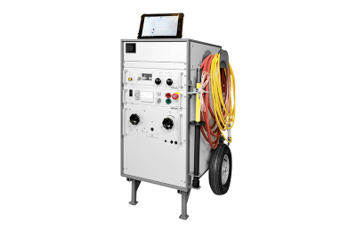
The Syscompact 400 Portable from BAUR is a comprehensive system for fault location in medium-voltage insulated cables, including cables with a nominal voltage of 20/35 kV.

BAUR's CL 20 is an instrument designed to trace the route of underground cables and metallic pipes with precision at depths of up to 15 meters.

With protrac®, it is possible to precisely locate acoustic, electromagnetic, and sheath faults in insulated cables, as well as trace circuit routes.